
Category | Item | Quantity/Specification |
Safety Protection | Insulating Gloves (Live-line Grade) | 2 pairs |
Safety Protection | Insulating Boots | 2 pairs |
Safety Protection | Safety Helmets | 2 pcs |
Safety Protection | Safety Harness / Fall Arrester | 2 sets |
Safety Protection | Insulating Shield Covers | 1 set |
Installation Tools | Insulating Operating Rod | 1 pc (Length ≥2m) |
Installation Tools | Torque Wrench | 1 pc |
Installation Tools | Hex Key Wrench Set | 1 set |
Installation Tools | Wire Stripper | 1 pc |
Installation Tools | Multimeter | 1 pc |
Auxiliary Equipment | Insulated Aerial Work Platform (or UAV) | 1 unit |
Auxiliary Equipment | Walkie-Talkies | 2 pcs |
Materials | Warning Light Unit | As required |
Materials | Mounting Bracket / Clamp | Matching set |
Materials | Stainless Steel Bolts M8×30 | Matching set |
Materials | Insulating Tape | 2 rolls |
Materials | Anti-Rust Grease | As needed |
Voltage Level | Min. Safe Distance (m) | Min. Insulating Rod Length (m) |
10kV | 0.7 | 0.7 |
35kV | 1.0 | 0.9 |
110kV | 1.5 | 1.3 |
220kV | 3.0 | 2.1 |
Step 1: Positioning: Park the insulated aerial work platform directly below the conductor at an appropriate position with outriggers firmly supported. Workers wearing insulating protective equipment enter the insulated bucket and raise to the conductor installation height.
Step 2: Mounting Bracket Fixation: Place the warning light mounting bracket (or clamp) over the conductor, using the insulating operating rod for auxiliary positioning. Ensure the bracket opening direction is correct and the conductor is centered in the bracket.
Step 3: Bolt Tightening: Use a torque wrench to gradually tighten mounting bolts in diagonal sequence according to product specifications (typically 15~25N·m). Ensure the bracket is in tight contact with the conductor with no looseness.
Step 4: Warning Light Unit Installation: Align the warning light unit with the mounting bracket slot or connection holes and push into place. Secure connection bolts with hex key wrench and confirm correct light orientation (LED face downward or toward warning direction).
Step 5: Induction Power Coil Installation: Place the current transformer (CT) over the conductor, ensuring the conductor passes through the center hole of the CT. Secure the CT housing and check for good contact between the coil and conductor.
Step 6: Inspection and Testing: Confirm all connections are secure with no looseness or detachment. Cover the photosensitive sensor with hand to simulate nighttime environment and observe whether the LED flashes normally.
Step 7: Withdrawal: Clean up the work site and recover tools. Workers slowly lower the insulated bucket and withdraw to a safe area.
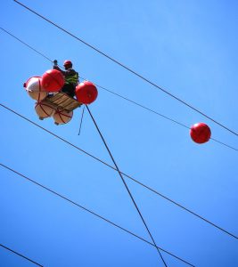
Step 1: UAV Preparation: Select an industrial-grade UAV with payload capacity ≥5kg and install a dedicated mounting device. Pre-assemble the warning light unit with the mounting bracket to ensure structural integrity.
Step 2: Flight Positioning: Control the UAV to slowly ascend to the conductor installation position, maintaining a safe distance ≥3m from energized conductors. Adjust UAV position so the warning light aligns with the target conductor.
Step 3: Hanging Operation: Use the UAV mounting device’s robotic arm or clasp mechanism to hang the warning light onto the conductor. Some products use a safety hanging strap design where the strap loops over the conductor and connects to the light body for fixation.
Step 4: Locking Confirmation: Observe via UAV camera to confirm the mounting bracket is locked and the warning light is stable without swaying. If equipped with an electric locking mechanism, remotely control the locking operation.
Step 5: Return and Inspection: The UAV slowly withdraws and hovers at a safe distance to observe the warning light installation status. Return and land after confirmation.
Step 6: Ground Verification: Observe whether the warning light flashes normally at night to confirm successful installation.
[UAV Installation Advantages] Suitable for complex terrain areas inaccessible by insulated aerial work platforms (such as mountainous regions or above rivers). Lines below 40 meters can be completed within 2 minutes, significantly improving operational efficiency, reducing labor and material costs, and effectively reducing transmission line tripping rates.
Step 1: Pole Positioning: Workers climb the pole to the conductor cross-arm position and secure the safety harness to the pole.
Step 2: Pre-Assembly: Pre-assemble the warning light with the mounting bracket on the ground and hoist it to the pole using an insulating rope.
Step 3: Hanging and Fixation: Use the insulating operating rod to hang the mounting bracket onto the conductor and tighten the fixing bolts through the rod’s rotation mechanism.
Step 4: Inspection Confirmation: Visually inspect installation firmness and confirm correct warning light orientation.
Inspection Item | Acceptance Standard | Inspection Method |
Installation Firmness | No looseness, sliding, or tilting | Manual shake / Visual inspection |
LED Flashing Function | Auto-flash at night, auto-off in daytime | Cover photosensitive sensor test |
Flashing Frequency | 1Hz~2Hz (or per product rating) | Stopwatch / Visual observation |
Visible Distance | ≥800m at night | Field measurement at night |
Waterproof Performance | No water ingress or condensation | Post-rain inspection / Water spray test |
Insulation Performance | Equipotential design, no line impact | Live detection / Operation monitoring |
Fault Symptom | Possible Cause | Remedy |
LED Not Lit | Line current below startup; CT coil fault; LED damage | Confirm load current; measure CT output; replace LED |
LED Constantly On | Photosensitive sensor fault; control circuit fault | Check/replace photosensitive sensor; repair control circuit |
Abnormal Flashing | Control circuit fault; unstable power supply | Check voltage regulator; check CT power harvesting status |
Brightness Degradation | LED aging; lens contamination | Replace LED module; clean lens |
Water Ingress | Seal failure; gasket aging | Replace seals; re-apply waterproofing |
Loose Installation | Bolt looseness; bracket deformation | Re-tighten; replace bracket |
[Diagram 1] Live-line installation via insulated aerial work platform: Platform → Workers → Bucket → Conductor → Warning Light
[Diagram 2] UAV-assisted installation: UAV → Mounting Device → Warning Light → Conductor
[Diagram 3] Warning light structure: LED Face → Photosensitive Sensor → CT Power Coil → Mounting Bracket → Safety Strap
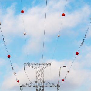
[Diagram 4] Installation location: High-voltage conductors crossing highways/bridges/construction zones
|
|
Installation Date |
|
Installation Location |
|
Line Name/Number |
|
Voltage Level |
|
Conductor Type/Diameter |
|
Warning Light Model/Number |
|
Installation Method | □ Insulated Aerial Platform □ UAV □ Insulating Operating Rod |
Workers |
|
Supervisor |
|
Weather Conditions |
|
Pre-Installation Check | □ Exterior intact □ Accessories complete □ Parameters matched |
Post-Installation Test | □ LED flashing normal □ Light control normal □ Installation firm |
Acceptance Conclusion | □ Pass □ Fail |
Remarks |